
Replacement timing screws
Manufacture replacements from a component, scan, drawing or approved specification.
Every bottle. In the right place.
Give your containers the spacing, orientation and timing they need. Feed screws designed around your bottles and existing machine.
3 weeks standard · 1 week rushDelivery schedule and suitability confirmed in your offer.
A few dimensions. An offer for your application.
Explore the material, finish and design first.
Request a free demo part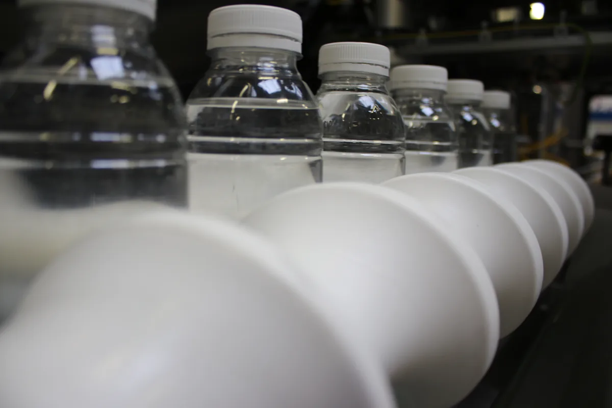
On the production line
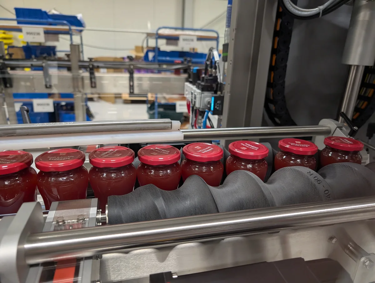
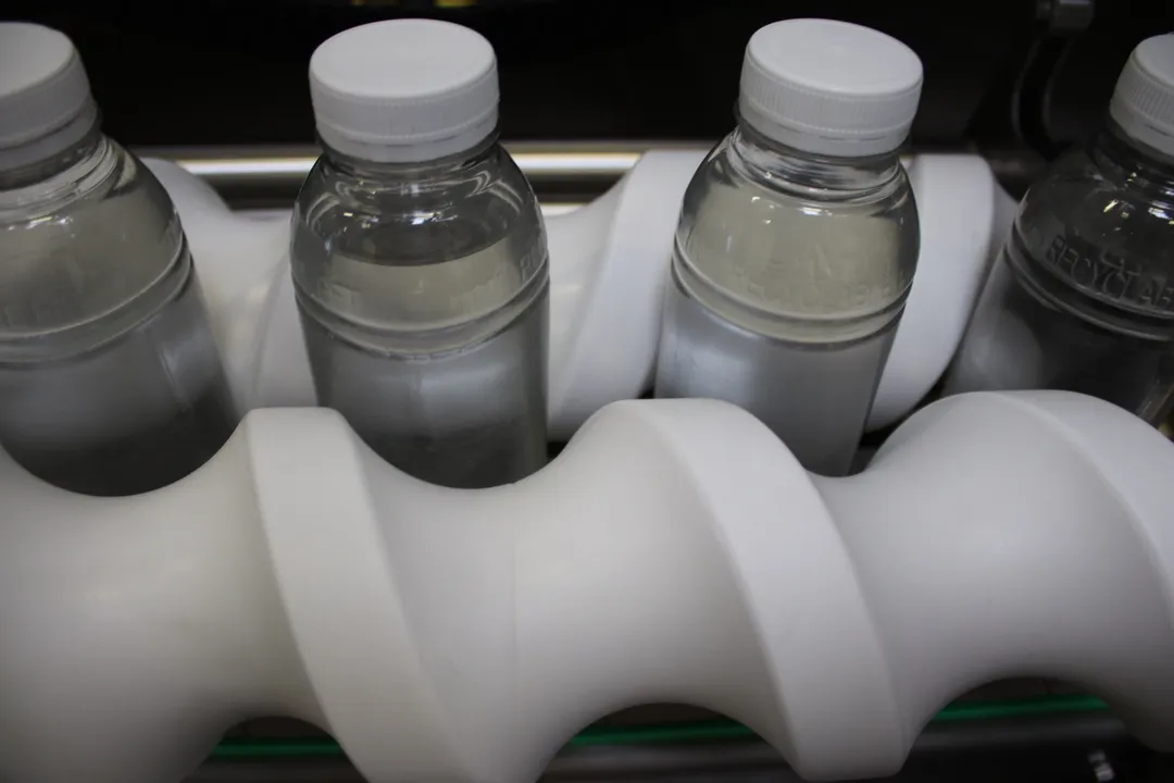
Watch an AddPack timing screw guide jars through the machine. Take a closer look at the installed part, the container and the guides around it.
Use cases
Timing screws coordinate product movement, spacing and orientation across demanding packaging applications.
Manufacture replacements from a component, scan, drawing or approved specification.
Meter products into a controlled spacing for downstream machinery.
Transition container pitch and timing between process stages.
Manage product flow and lane transitions around the application.
Rotate or present suitable containers to a required position.
Control and guide containers with paired, synchronised screws where needed.
Engineering & configurations
The geometry is evaluated against the container, transfer and machine interface. Where useful, the component can be optimised rather than copied.
For applications requiring a consistent feed interval.
Tailored transitions in container spacing or motion.
Geometry selected around the container and machine interface.
Practical construction for longer or machine-specific installations.
Reverse engineer an existing screw or develop geometry from a new application.
Timing screws meter, space, divide, accelerate, decelerate and present containers through a packaging line. The pitch profile, mounting arrangement and material are selected around the actual container, transfer and line duty.
Critical geometry, interfaces and the selected assembly method are checked against the agreed design before dispatch. The validated digital manufacturing specification is retained for controlled repeat production.
How we work
Send a drawing, container model, part photograph or machine reference.
We consider how the container must move and what machine interfaces matter.
Confirm the design, method and agreed inspections before release.
Keep the approved manufacturing geometry available for repeat supply.
Make an enquiry
A worn screw, container dimensions, machine reference, photographs and a target application are all useful. You do not need a complete CAD model to begin.
Request an offerPhotographs of the container or existing component
Drawings, STEP, PDF or related machine information
Quantity, application and required timing
Good to know
Common starting points for specifying and ordering made-to-fit parts.
Depending on the container and surrounding machine equipment, profiles can control pitch, accelerate or decelerate, separate flow or orient a product. The feasible movement must be confirmed for the application.
A physical part, photographs, dimensions, shaft arrangement, container information and machine requirements can provide an engineering starting point. Critical geometry and interfaces still require validation.
Segmented construction can be considered where length, assembly or manufacturing requirements justify it. The joining and retention method are selected against the application and machine interfaces.
After a design has been validated and its manufacturing specification retained, repeat supply can normally reference the approved design. Changes in duty, material or fit may still require review.
Yes. Photographs and machine details are useful for starting a technical discussion. Additional dimensions or sample parts may be requested before a final manufacturing specification can be released.
Lead times depend on geometry, quantities, material availability, finishing and required validation. AddPack confirms a project-specific delivery commitment when reviewing a quote request.
Real AddPack application footage. No simulated machinery and no stock substitute.
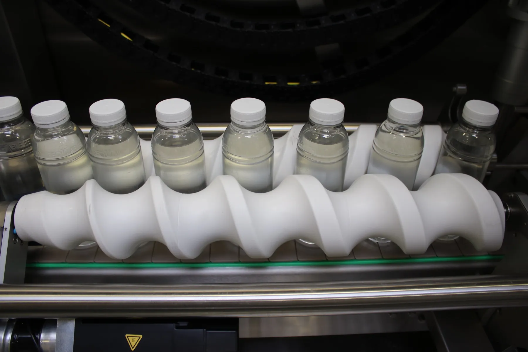
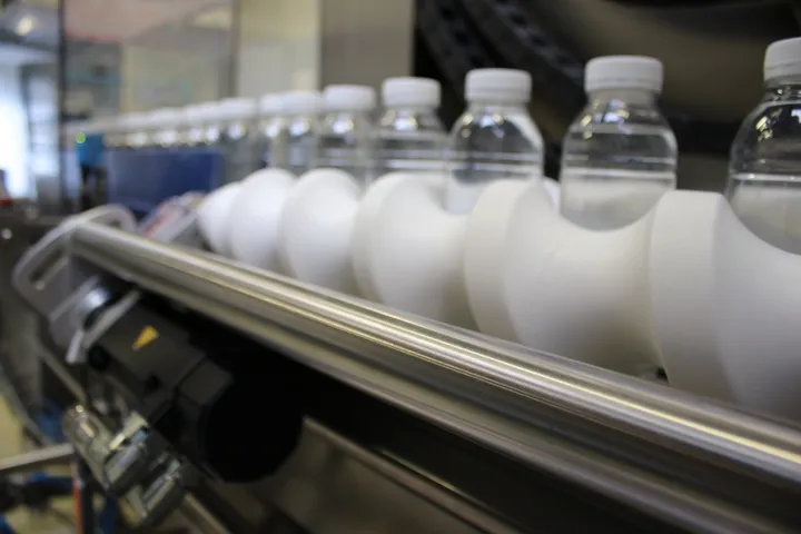
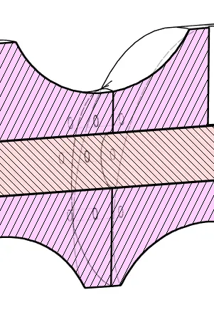
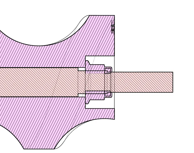
Technical illustration
Explore component geometry and format options in this engineering illustration. Final dimensions and interfaces are designed for each packaging line and container.

Your next step
Share a photo, drawing or a few dimensions. Our engineers will review your application and prepare an offer.
Explore a real part first.
Request a free demo part